
While these standards are for 1:32 scale wheels, they are also applicable to other scales operating on gauge 1 track (i.e. 1:225., 1:20.3, et al.). The "IF" measurements are for use with "finescale" wheels. For the larger scales, the flanges and treads come closer to representing actual scale tread sizes.
I would recommend that those turning wheel castings to a finished profile consult an article in Model Engineer magazine (Vol. 161, No 3832, p. 282) entitled "Wheel Turning". Author Barry Applegate describes a prodecure for assuring that all the diameters on the wheel are concentric after turning. (This is not as easy as it would appear before you have done it!)
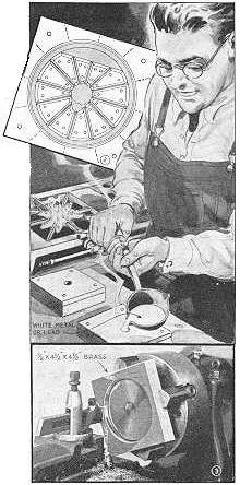

 ODELMAKERS who build
locomotives
need not go to the expense of purchasing the wheels, Fig. 1, if
they
cast
them in these brass molds, which can be used repeatedly. The molds
shown
are not dimensioned to a particular scale, but by following the
instructions
you can make them to any desired scale. All you need is two small
pieces
of brass, one a little thicker than the wheels to be cast to serve
as
the
mold, and the other to serve as a cover.
ODELMAKERS who build
locomotives
need not go to the expense of purchasing the wheels, Fig. 1, if
they
cast
them in these brass molds, which can be used repeatedly. The molds
shown
are not dimensioned to a particular scale, but by following the
instructions
you can make them to any desired scale. All you need is two small
pieces
of brass, one a little thicker than the wheels to be cast to serve
as
the
mold, and the other to serve as a cover.
![]() First, chuck
the
thick
piece in a lathe and turn it to form a profile of the wheel to be
cast,
Fig. 3. Turn the depression for the hub, tire and tire flange, and
then
turn the rest of the profile to equal the thickness of the spokes.
Be
sure
to allow a 2-degree draft or taper on the hub and tire-flange
depressions.
This is necessary to assure easy removel of the casting. It may be
necessary,
after turning the hub depression, to use a mill to elongate it to
form
the crank lug.
First, chuck
the
thick
piece in a lathe and turn it to form a profile of the wheel to be
cast,
Fig. 3. Turn the depression for the hub, tire and tire flange, and
then
turn the rest of the profile to equal the thickness of the spokes.
Be
sure
to allow a 2-degree draft or taper on the hub and tire-flange
depressions.
This is necessary to assure easy removel of the casting. It may be
necessary,
after turning the hub depression, to use a mill to elongate it to
form
the crank lug.
![]() The next step
is
to cut
segments and rivet them in the mold to form the spokes, Fig. 2.
These
can
be cut from brass on a jigsaw, using a jeweler's blade. Tilt the
saw
table
at a 2-degree angle to taper the segment edges to get the
necessary
draft.
Now, cuts or scores should be made in the face of the mold from
each
spoke
position as indicated by the dotted lines in Fig. 2, to allow air
to
escape
when pouring the metal.
The next step
is
to cut
segments and rivet them in the mold to form the spokes, Fig. 2.
These
can
be cut from brass on a jigsaw, using a jeweler's blade. Tilt the
saw
table
at a 2-degree angle to taper the segment edges to get the
necessary
draft.
Now, cuts or scores should be made in the face of the mold from
each
spoke
position as indicated by the dotted lines in Fig. 2, to allow air
to
escape
when pouring the metal.
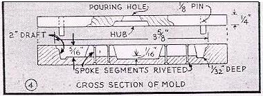
![]() The upper half of the mold is quite simple to make. It is fitted
with
four
pins to engage holes in the lower half of the mold. A tapered hole
is
bored
out on the lathe to form a hub for the inside of the wheel, and is
continued
right through the plate by drilling, Fig. 4. This hole is for
pouring
and
should be countersunk on the inside to permit easy removal from
the
casting.
Before using the mold, it should be heated slightly and smoked
well on
the inside.
The upper half of the mold is quite simple to make. It is fitted
with
four
pins to engage holes in the lower half of the mold. A tapered hole
is
bored
out on the lathe to form a hub for the inside of the wheel, and is
continued
right through the plate by drilling, Fig. 4. This hole is for
pouring
and
should be countersunk on the inside to permit easy removal from
the
casting.
Before using the mold, it should be heated slightly and smoked
well on
the inside.
 Go
to
table of contents.
Go
to
table of contents.
Copyrights owned by the respective authors. Compiled by: Vance R. Bass. All rights reserved. Please use any and all information contained herein for your hobby enjoyment. If you're going to make money from it, talk to me first.
Last updated: 14 Feb. 1999.