boat

Pop-pop engines, or water-impulse engines, as Basil Harley calls them in his book, Toyshop Steam, date back a hundred years or so. Their origins are obscure, which adds to their charm and mystery.
The pop-pop engine is simply a tube of copper, with or without a coil or coils, that has both ends in the water. The middle of the tube is heated and the boat in which it is installed goes.
How these work, in scientific terms, is still open to conjecture and it has been the source of some controversy. What appears to happen is that a little water in the tube flashes into steam, forcing the rest of the water out the back, making the boat go forward (see one of Newton's various laws). The vacuum thus created within the tube draws in more water and the cycle repeats.
In practice there are many variables, as follows: the length and diameter of the tube, the heat source, the weight of the boat, and whether or not the flame is shielded. Any and all of these will affect performance. Admittedly, I have not seen a great many pop-pops actually at work, but of the ones I've seen, none put on a performance that I would call great, or even good. However, if one considerably lowers one's standards, a well-designed pop-pop boat will perform in a manner that could be described as acceptable.
Pop-pops have always been the stepchildren of the steamboat family. They can truly be called steamboats, but they bear little resemblance to a proper steamboat. They have no moving parts, after all. Not even one! In the early days of pop-poppery, the German manufacturers often built a thin, flexible metal diaphragm into the water/steam circuit. This diaphragm was dished slightly and, when the water flashed into steam, the thing would spring out, making a noise like a metal cricket that you snap by pressing it with your thumb. That's how the boat got its common name. (The Germans call them toc-toc boats for the same reason.)
 Building
a pop-pop boat is a good exercise in simple sheet-metal work. You can
build it out of brass, but I prefer tinplate from an old paint-thinner
can. If you use brass, don't build the boat from anything more than
.010" thick.
The hull I show here can be made from a single piece of metal. I have deliberately not included any type of superstructure. You can be as creative as you like here. I've only included the bare minimum required to get a boat working in the water.

Hull pattern (click on image to get full-sized pattern).
Drill the holes for the water tubes. Then cut the sides and the transom (back end), but do not cut around the bow (front end). Leave the bow a flat chunk for now (see the photo). Carefully fold the three tabs. This can be done in a vise or with some long, flat-nose pliers.
In a vise, fold up the sides and the transom so that they meet. Adjust the tabs to fit, if necessary. The sides, as they come together to form the prow, will define the shape of the front of the boat.
Solder the transom to the sides. I like to use a small torch, but a resistance solderer will also work. If you are good with an iron, that should work fine, too.
The bow should now form a floor upon which the sides rest (see the photo). Solder the two sides together at the prow, then run a good bead of solder all around the bow where it joins the sides. When everything is solid and water tight, trim around the bow of the boat with snips, cutting as close to the sides as possible. File the rough edges flush, and the hull is complete.

1. The cut-out hull with the pattern removed.

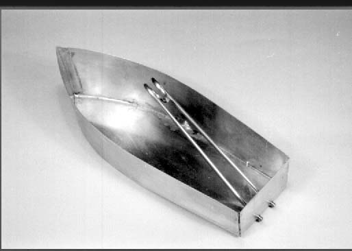
2. The hull has been folded and soldered together. The floor of
the bow has not yet been trimmed to shape.

3. The finished hull after a going over with some steel wool.

4. Bending the 3/32" copper coil around the 1/2" wooden dowel.
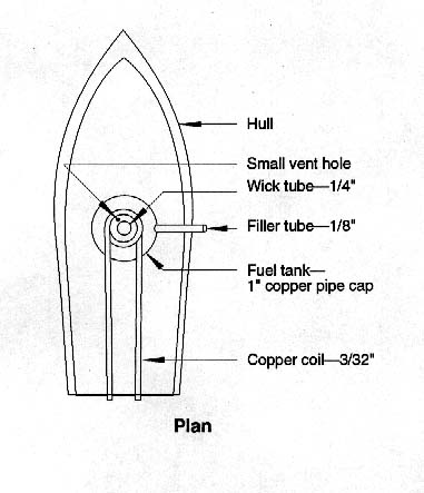
Bend the legs so that, when the coil is installed, small extensions protrude from the rear of the boat, more or less level, while the coil is elevated to working height (see photos and drawing). Insert the two legs into the two holes and position the coil. You should have plenty of extra copper sticking out. Trim the ends, leaving the tube in its final configuration. Position the coil properly (you may need to temporarily prop it up) and solder the unit in place.

5. The coil soldered into the hull.

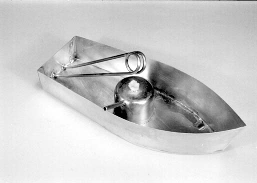
6. Burner parts. The tank is a 1" copper pipe cap.
Cut a small piece of 1/4" OD brass or copper tubing and solder it in place. Soft solder is fine. The 1/8" hole is for the filler tube. Solder a piece of 1/8" tubing into this hole and bring it out to the side, away from the flame. Cut and fit some fiberglass wick material, and you're done with the basic unit. The rest is up to you.

7. The finished boat, lacking only a rudder and cosmetics.
If your boat does not sit low enough in the water, you may need to add some ballast. This can be just about anything-metal ingots, lead tire weights, pennies, sand, broken locomotive parts, etc.
There is any amount of room for creativity in the area of building a superstructure for your boat. I've just given you the bare essentials here. This is a wonderful project in which to let yourself run amuck, as you should have little time invested in its creation up till now. In other words, if you ruin it, you're not out much.
Performance in the boats I've seen tends to be erratic. Perhaps someone with more experience in these matters will have better information. In some instances, the boat will have impressive spurts of energy during which it will appear to actually have some ambition. At other times it will just putter along at a most sedate speed. The amount of heat directed on the coils appears to have a definite effect on performance, which makes sense. I suggest that you try experimenting to determine optimum wick height. Let us know your results.
I found that my test boat would greatly benefit from a rudder of some sort. This could be nothing more than a rudder-shaped piece of metal soldered to the transom and extending into the water. If you want to get fancy (and who doesn't, sometimes?), then a moveable rudder could be fashioned.
So, consider this article as an invitation to attend and participate in the Second Annual Pop-Pop Regatta in Mississippi in 1998. I look forward to seeing what bits of bush engineering, ingenuity, and whimsey you end up producing in this obscure field.
And finally, since I'm not a proper boat guy, I must apologize to those who are for any improper use of boat terminology.

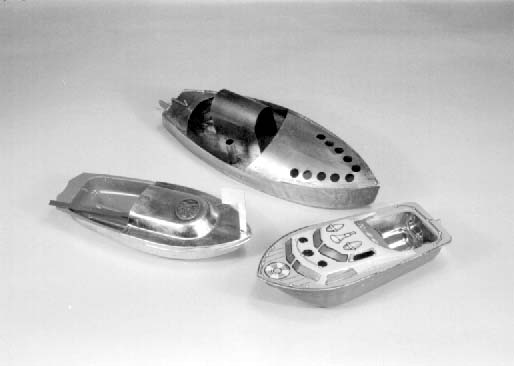
8. A selection of other pop-pops. The two in front are
current
commercial products; the one on the right is from China and the one on
the left is from India. Both are fitted with the popping diaphragm.
I've heard good reports regarding their performance. The boat in back
was built by the Author and has an inverted-U shield over the coil and
flame. It is also fitted with a moveable rudder.